PATENT SPECIFICATION UK 320033
Application: June 1, 1928, No. 16,017/28. 320033 Accepted : Oct. 1, 1929.
PROVISIONAL SPECIFICATION.
Improvements in Paddle Mechanism for Circulating Molten Glass.
We, John Moncrieff Limited, a British Corporation, having its registered offices at St. Catherine’s Road, Perth, Scotland, and Alexander Francis McNish, of 25, Balhousie Street, Perth, aforesaid, citizen of the United States of America, do hereby declare the nature of this invention to be as follows :—
This invention has reference to improved paddle mechanism for circulating molten glass through the forehearth of a glass furnace or through any similar trough or channel.
According to my invention, the paddle is carried by a holder or arm which is oscillated about a fulcrum reciprocated vertically and so situated that it requires only a small opening in the cover of the forehearth for the passage of the paddle through the cover. The fulcrum consists of a pin on the paddle holder journalled in a slide guided vertically by suitable guides and reciprocated by means of a rotating cam. The paddle is oscillated about its fulcrum by means of a crank pin which works in a slot in the paddle holder. The cam is shaped to give the desired vertical stroke to the paddle and preferably coacts with a roller adjustably or otherwise mounted on the slide which may be guided by means of fixed vertical guide rods passing through cross heads on the slide.
The throw of the crank-pin determines the stroke of the paddle in a horizontal 35 direction and the cam and crank-pin are so situated in relation to one another that the paddle is first dipped into the glass, then rocked in one direction about its fulcrum to move the paddle through the glass in the trough or forehearth, whereupon the paddle is raised out of the glass and finally rocked back again about its fulcrum.
The paddle arm is preferably of inverted shape, its shorter horizontal limb supporting the upper end of a clay or other refractory paddle which passes through a conical opening formed in a block of clay or other refractory material which closes the opening in the cover of the forehearth. The vertical limb of the paddle arm is provided at a short distance from its upper end with a projecting horizontal fulcrum pin and is formed at its lower end with a vertical slot which cooperates with a crank pin conveniently mounted on one side of the cam.
Dated this 31st day of May, 1928.
JOHNSONS,
Chartered Patent Agents, 41, St. Vincent Place, Glasgow,
and 10, Stafford Street, Edinburgh.
COMPLETE SPECIFICATION.
Improvements in Paddle Mechanism for Circulating Molten Glass.
We, John Moncrieff Limited, a 60 British Corporation, having its registered offices at St. Catherine’s Road, Perth, Scotland, and Alexander Francis McNish, of 25, Balhousie Street, Perth, aforesaid, citizen of the United States of 65 America, do hereby declare the nature of this invention and in what manner the same is to be performed, to be particularly described and ascertained in and by the following statement :—
This invention has reference to improved paddle mechanism for circulating molten glass through the forehearth of a glass furnace or through any similar trough or channel.
The present invention consists in mounting the paddle holder on a horizontal fulcrum which is reciprocated vertically to raise and lower the paddle and to cause it to dip into the glass, whilst mechanism is provided to rock the paddle to and fro so that it travels in one direction in the glass and returns when raised out of the glass. By this construction the fulcrum can be so situated that it requires only a small opening in the cover of the fore-hearth for the passage of the paddle through the cover.
In order that the invention may be more clearly understood, reference is made to the accompanying drawings showing improved paddle mechanism according to this invention.
The paddle 4 has a shank 5 which is carried by a paddle holder 6. The fulcrum consists of a pin 7 on the paddle holder journalled in a slide 8 guided vertically and reciprocated by means of a rotating cam 10. The paddle holder 6 is oscillated about its fulcrum 7 by means of a crank pin 11 which works in a slot 12 in the paddle holder.
The cam 10 is shaped to give the desired vertical-stroke to the paddle 4 and preferably coacts with a roller 13 adjustably or otherwise mounted on the slide 8 which may be guided by means of fixed vertical guide rods 9 passing through cross heads 14 on the slide 8.
The throw of the crank-pin 11 determines the stroke of the paddle 4 in a horizontal direction and the cam 10 and crank-pin 11 are so situated in relation to one another that the paddle 4 is first dipped into the glass, then rocked in one direction about its fulcrum 7 to move the paddle through the glass in the trough or forehearth, whereupon the paddle 4 is raised out of the glass and finally rocked back again about its fulcrum 7.
The paddle holder 6 is preferably of inverted L-shape, its shorter horizontal limb supporting the core rod 15 of a clay or other refractory paddle which passes through a conical opening 16 formed in a block 17 of clay or other refractory material which closes the opening 18 in the cover 19 of the forehearth 20. The vertical limb of the paddle holder 6 is provided at a short distance from its upper end with the projecting horizontal fulcrum pin 7 and is formed at its lower end with the vertical slot 12 which cooperates with the crank pin 11 conveniently mounted on one side of the cam 10. The roller 13 may be adjustably mounted on the slide 8 by fitting it on a back plate 21 adjustably bolted to the slide 8.
The cam 10 is mounted on a cam shaft 22 which is rotated by any convenient means and the cam 10 is shaped to give the desired height of stroke and dipping movement. It will be noted also that the mechanism can be arranged outside the forehearth so that the paddle holder overhangs the outside wall of the forehearth.
Having now particularly described and ascertained the nature of our said invention and in what manner the same is to be performed, we declare that what we claim is :—
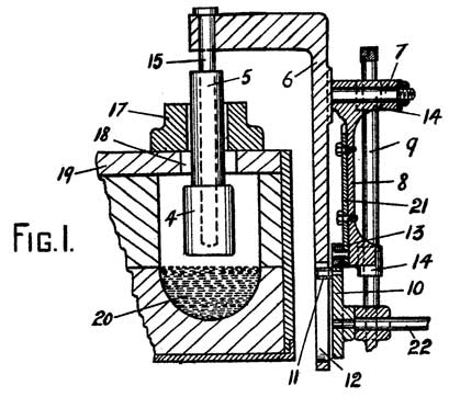
Fig. 1 is a vertical sectional view.
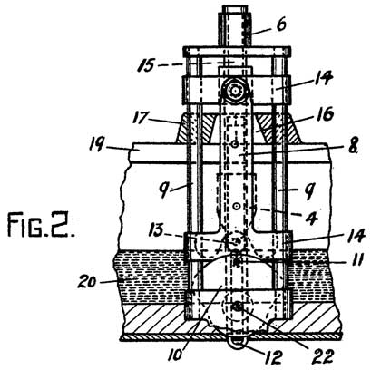
Fig. 2 is a view at right angles thereto, showing the forehearth in section.
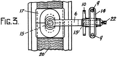
Fig. 3 is a plan view.
- Paddle mechanism for circulating molten glass through a trough, channel or forehearth, comprising a paddle holder, a horizontal fulcrum for said paddle holder, means for vertically reciprocating said fulcrum, and means for rocking the paddle holder about its horizontal fulcrum.
- Paddle mechanism for circulating molten glass as claimed in claim 1 in which the horizontal fulcrum is so situated that only a small opening is required in the cover of the trough, channel or forehearth for the passage of the paddle.
- Paddle mechanism for circulating molten glass as claimed in claim 1 in which the fulcrum is carried by a vertically-guided slide reciprocated by a cam having a crank pin which works in a slot in the paddle holder.
- Paddle mechanism for circulating molten glass as claimed in claim 3 in which the cam coacts with a roller adjustably mounted on the slide.
- Paddle mechanism for circulating molten glass as claimed in claim 1, 2 or 3 in which the paddle is first dipped into the glass, then rocked in one direction through the glass, thereupon raised out of the glass, and finally rocked back again over the glass.
- Paddle mechanism for circulating molten glass as claimed in claim 2 in which the glass trough is covered by a refractory cover having a conical aperture through which the paddle passes.
- Paddle mechanism for circulating molten glass according to any of the preceding claims in which the paddle shank is carried by the horizontal limb of a paddle holder of inverted L-shape, the vertical limb of which is supported by a horizontal fulcrum, substantially as described.
- The improved paddle mechanism for circulating molten glass through a trough, channel, or forehearth, constructed substantially as herein described and illustrated.
Dated this 21st day of November, 1928.
JOHNSONS,
Chartered Patent Agents, 41, St. Vincent Place, Glasgow,
and 10, Stafford Street, Edinburgh.